Wireless Battery Charger Chip Circuit Design
Wireless Battery Charger Chip Circuit Design - The herein circuit design provided a chip for inductive battery charging system which needs no external

Wireless Battery Charger Chip Circuit Design - The herein circuit design provided a chip for inductive battery charging system which needs no external component Wireless Battery Charger Chip Circuit
Designinstead of an antenna to capture electromagnetic energy field for being applied in smart-card applications.
The circuit is implemented to charge lithium cells (4mA 4.2V) to be targeted on the smart-cards with secondary batteries.
» Remote Unit Receiver Circuit Schematic using TDA7000
» TEA5711T Application Circuit Diagram and Datasheet
» TDA8160 Pinout Schematic and Datasheet
» NE570D Compandor Lead Marking Diagram
» NE570 Compressor Typical Test Circuit and Datasheet
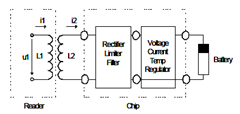
The figure shows schematic diagram of the charging architectural sytem. You will be taken into sections such the system architecture and the charging profile of rechargeable batteries,
description of the different blocks and their purpose (Mutual inductance coupling, Voltage limiter, Rectifier, Current regulation, Voltage regulation, Temperature control, Pass-element, OR-gate, Discharge stop), the overall chip and the measurement results.
Complete read on Wireless Battery Charger Chip for smart-card applications can be found in this Circuit Design article of pdf filetype (source: iis.fraunhofer.de)
Tags: Wireless Circuit Design, Battery Charger Chip, Battery Charger Circuit,
Related Wireless Battery Charger Chip Circuit Design Posts in Wireless Category» Remote Unit Receiver Circuit Schematic using TDA7000
» TEA5711T Application Circuit Diagram and Datasheet
» TDA8160 Pinout Schematic and Datasheet
» NE570D Compandor Lead Marking Diagram
» NE570 Compressor Typical Test Circuit and Datasheet
Copyright www.unboxing.eu.org

