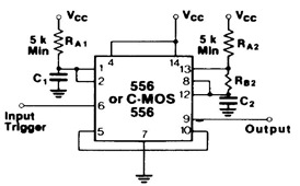
555/556 Tone Burst Generator Circuit Diagram
555/556 Tone Burst Generator Circuit Diagram - The 556 timer is a dual version of the 555 single timer, they suitable for monostable or astable operat

555/556 Tone Burst Generator Circuit Diagram - The 556 timer is a dual version of the 555 single timer, they suitable for monostable or astable operation. It results in providing effective solutions for timing and pulse circuit applications.
The picture shows you with Tone Burst Generator Circuit Diagram using the 556 dual timer. It is connected as a one shot circuit. The pulse established by one shot turns on the oscillator allowing a burst of pulses to be generated.
You can see more about 555 timer datasheet here in this blog.
(source: et-inf.fho-emden.de)
Tags: 555 Timer Datasheet, tone burst generator, 555 tone burst circuit,
Related 555/556 Tone Burst Generator Circuit Diagram Posts in Counter/Timer Category» Fire Smoke Detector Circuit Diagram Operation System
» NE570/NE571 High Level Limiter Circuit Schematic
» MF10 Full Duplex Modem Filter Diagram Schematic and Applications
» LM324 Active Bandpass Filter Circuit Diagram
» LM2576 in the Battery Charging Circuit Application
Copyright www.unboxing.eu.org

