5V 4A Step-Down Regulator Circuit in Forward Converter Topology
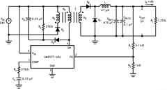
5V 4A Step-Down Regulator Circuit in Forward Converter Topology - In the following article you will be provided with a 20W, 5V at 4A, step-down regula

5V 4A Step-Down Regulator Circuit in Forward Converter Topology - In the following article you will be provided with a 20W, 5V at 4A, step-down regulator which is developed using 5V 4A Step Down
Regulator Circuit in Forward Converter TopologyLM2577 “Simple Switcher” in a forward converter topology. This topology can easily provide galvanic isolation between input and output.
In the depth of the article there are sections describe the design procedures which begins with the transformer design, the output filter and snubber circuit design. As you can see in the diagram, Diodes (Dr and Df are 5A, 30V Scottky diodes which is the same type used for Dc).
The regulator’s stability are optimized by the Rc and Cc compensation network and provides a soft-start function for a well-controlled power-up.
Read completely about the design procedures of 5V 4A Step-Down Regulator Circuit in Forward Converter Topology in this circuit application article here (source: national.com).
Tags: circuit design, step down regulator, forward converter,
Related 5V 4A Step-Down Regulator Circuit in Forward Converter Topology Posts in Datasheet Application Category
» Fire Smoke Detector Circuit Diagram Operation System
» NE570/NE571 High Level Limiter Circuit Schematic
» MF10 Full Duplex Modem Filter Diagram Schematic and Applications
» LM324 Active Bandpass Filter Circuit Diagram
» LM2576 in the Battery Charging Circuit Application
Copyright www.unboxing.eu.org

